BRAKE BOOSTER REBUILD KIT
AND OVERHAUL INFO
COVERS ATE H31 HYDRAULIC
BOOSTERS USED ON
BMW E24, E32, AND E31
MODELS, ALSO SOME AUDIS
There
are 3 options for buying rebuild kits:
A- The simple front leak kit, which is a seal and an o-ring. This is
adequate to fix the most common leak, but doesn't address any internal working
parts. The way to buy this is to send $6 US cash plus a self-addressed stamped
envelope to:
FINE MOTORING.COM
LUMMI ISLAND WA
Or you can simply Paypal $10 and I'll do the rest of
the shipping details, to “paypal@finemotoring.com”.
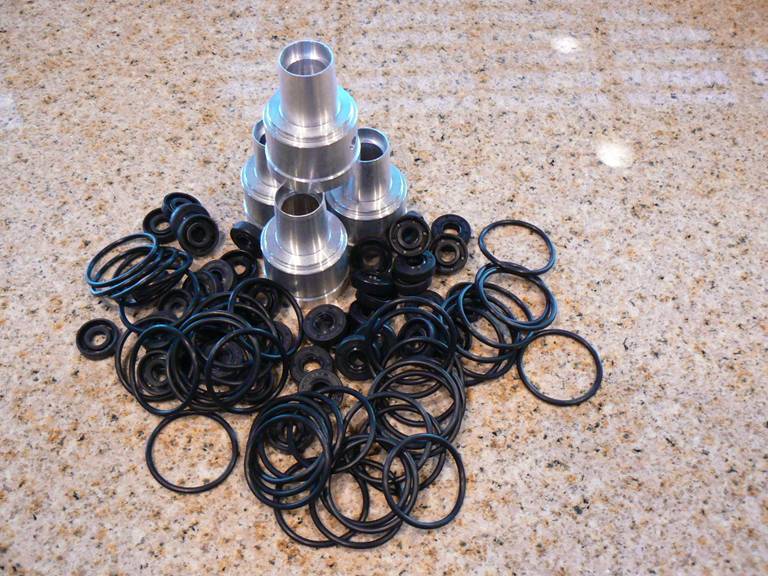
B- The rest of the seals and o-rings to do a full rebuild of the internal
working components and seal the shaft leading to the car interior. For this you Paypal $55 to "paypal@finemotoring.com",
or mail a check to the above address.
C- An upgrade aluminum seal-carrier cone. This is insurance against breaking
the OEM plastic cone during the seal swap. It's old plastic and not hard to
break. I figure guys will buy these and then possibly sell them along if they
succeed with the seal swap into the OEM cone. Or not; given the singularity of
the process, why not upgrade?
This part is $60 including shipping USPS priority with special protective
packaging. You can get any combination of the above kits, and all three
together will be $120 shipped.
Basic
R&R info for the booster and master cylinder can be found at BMWTIS
-- Repair Information. Opinions
differ on the degrees of difficulty for the various facets of this job. I have
only ever removed both cylinders from the car to replace any seals. Others have
said that the master cylinder doesn’t have to be uncoupled from its lines in
order to get to the booster and the seals can be done in situ. There’s nothing
challenging about rebuilding the internals; it’s a simple matter of swapping
o-rings and seals and you only need common hand tools. The new polyurethane
rear seal is a little balky, and it helps to heat it in oil before folding and
manipulating it into the groove.
You need to use quite a bit
of heat (hot to the touch) on the plastic cone to get it to soften, with a heat
gun or hair dryer. It’s some sort of glass-filled vaguely-thermoplastic stuff,
easy to crack if cold.
Below
are a variety of seal replacement and overhaul/rebuilding notes from other
guys, shamelessly swiped from around the interweb,
with gratitude to them for their conscientious and generous attitude about
detailing their process with notes and photos:
…
finally caved and started overhauling the brake booster O-ring, which I
suspected was the cause of the slight Pentosin leak underneath
the car.
I dutifully pulled everything apart and discovered a shrunken O-ring rattling
around in its groove. Replace it with the NAPA 727-2222 part, or tried to.
Discovered that if you don't have the set screw flush with the booster bore,
pushing the oversized O-ring in will nick it as it passes over the set screw
hole. A new leak will ensue shortly. I recommend deburring
the set screw hole prior to pressing in the new, and slightly oversized,
O-ring.
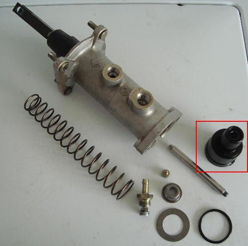
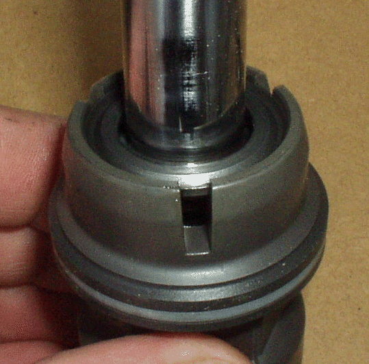
So, having figured that out, I reassembled the whole thing and pressurized. Now
I'm getting a small leak, but I suspect it's from the front cup assembly's (see
red below) shaft seal bushing.
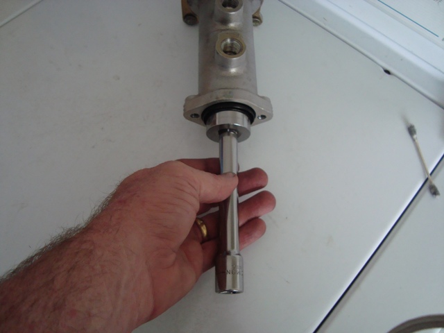
Well,
just finished R&R the plunger/shaft seal. Removal was pretty easy having
made a kluged-up removal mandrel consisting of a long 1/4" screw, some
washers and a bolt, combined with a semi-deep socket:
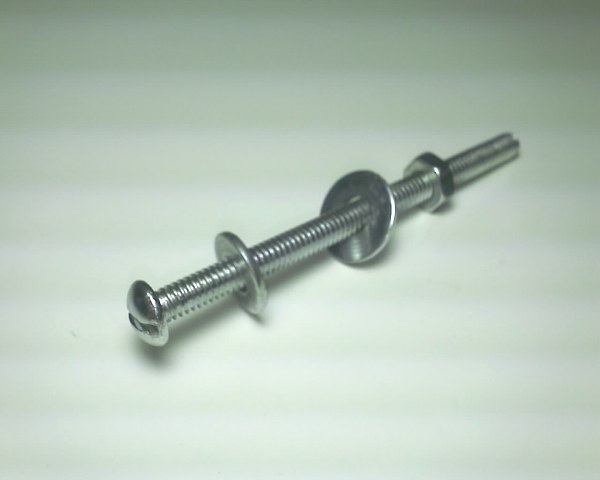
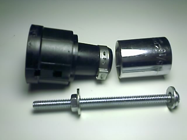
I threaded a
large washer onto the "inside" facing of the seal, pulled the screw
through the seal and mounted a 15/16" socket (1/2" drive) onto the
"nose" of the cup to provide some area to pull the seal. Again,
another washer and then finally the nut:
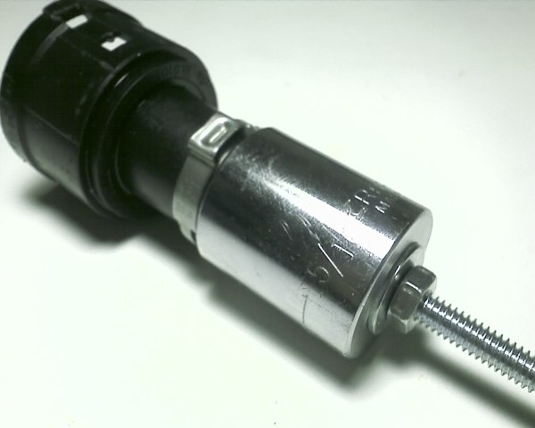
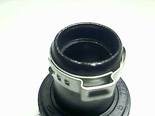
You might
notice that clamp around the nose of the cup. I lightly crimped an Oetiker 22mm clamp for provide strain support for all these
operations, but in reality you probably don't need one if you proceed very
carefully.
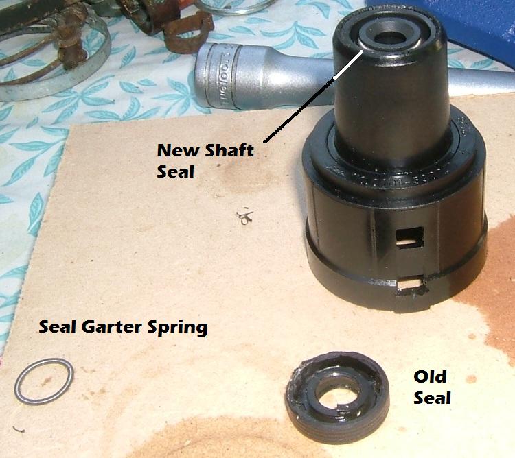
With a decent number of wrench turns, the seal is smoothly pulled from the cup
nose recess. Part 1 is now complete:
Installing the
new seal was, frankly, a bitch. I tried doing the screw/socket/mandrel thing in
reverse, but the seal's rubber coating buckled severely as it was forced into
the cup bore. The bore is undersized and relies on the compressibility of the
rubber coating to squeeze into the bore and provide a tight seal. So, after a
few e-mails to the ATE Brake Booster Brain (i.e., Max Lumens), the classic
"shop vise squeeze" technique was tried.
Max recommended sanding down the lip a bit to provide some bevel to help start
the new seal into the bore. Some 150 grit sandpaper did the trick. Next I
placed a 32mm 1/2" drive socket into the big end of the cup. The socket
protrudes from the cup and rests on the first shoulder inside the cup, and
takes the compressive forces that the rather fragile lip might bear. On the
seal side, I placed some flat shim steel to evenly distribute forces over the
width of the seal. Next I placed the seal on the bore lip, dribbled some dish
soap over the seal, and wound up the vise while heating the neck of the cup
with a hair dryer to provide some expansion (another suggestion from Max). The
seal moved smoothly into position. I had to push the seal completely home using
a small socket that matched up with the O.D. of the seal. Again, a little force
from the vise did the trick.
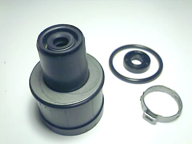
The new seal
feels much, much tighter around the plunger. We'll see if it solves the
problem. Stay tuned.
So, if you're getting the classic dribble from the booster weep hole, obviously
you should change the O-ring. But as you disassemble the entire gizmo,
carefully check down into the neck of the cup for any accumulations of Pentosin. I had some sloshing around down by the plunger
seal. Not thinking, I simply passed it off as some stray fluid buildup. Dumb.
Also, here's another trick to disassemble and reassemble the cup. I took a 32
mm 1/2" drive short socket with a 6" extension and inserted into the
cup prior to releasing the set screw. Makes it easy to walk/rock the
always-stuck cup out the first few millimeters, and then once it starts out, to
hold it against the considerable spring pressure:
It also helps installing the cup with the new O-ring. Line up the cup so the
cast index tab meets up with the recess in the casting, compress the spring,
and slightly rock/tip the cup back and forth to start it into the bore. That
1/2" extension gives you some mechanical advantage.
http://denmark.esar.org.uk/car/servo/
ATE Brake Servo
Rebuild
Servo Removal
|
|

|
|

|
|

- Pump brake pedal until it goes hard
- Remove spring clip from bottom of linkage pin and remove pin
- Remove split-pin and spring
- Syphon out brake fluid from master cylinder reservoir
- Disconnect brake lines from master cylinder
- Disconnect hydraulic pipes from servo
- Remove 4 bolts holding servo in place (loose nuts on back)
- Remove servo & master cylinder
- Place servo in a vice and remove the two bolts holding the master cylinder to the servo
Servo Disassembly
|
|

|
|

|
|

|
|

|
|

WARNING: The set screw is all that holds the servo components in, there is a large spring that will try and throw the components all over the place when you remove the set screw!
- Loosen set scew half a turn using mole grips
- Place servo on workbench master cylinder side down, push down with considerable force, remove set screw and slowly release downward force
- The servo components may be stuck in place by dried up hydraulic fluid, if so carefully prise out the plastic insert by placing a flat bladed screwdriver through the hole in the side of the plastic insert. At some point you'll break the resistance and if your not careful, everything will go flying. To prevent this place a pile of rags against a wall and place the servo an inch away so that the rags/wall prevent everything coming out.
- Gently remove remaining components, a pair of long-nose pliers wrapped in rags works fairly well.
Oil Seal &
O-Rings
|
|

|
|

|
|

|
|

Oil
Seal Replacement
|
|

|
|

|
|

|
|

|
|

WARNING: The plastic insert is old and brittle and irreplaceable
(short of a visit to a local machine shop), you really don't want to break it!
- Place a hose clamp around the neck of the plastic insert to prevent it expanding too much and shattering while removing the oil seal.
- With a flat bladed screw driver and small hammer, repeatedly hit the back of the oil seal on the same side until it rotates out. Be gentle, it took me the best part of an hour
- Thoroughly clean the plastic insert with a lint free cloth
- Lubricate the new seal with fresh ATF
- Press new seal in with a vise. I found it was necessary to start the seal off at a very slight angle to get it started and then straighten it up by pushing/pulling on the block of wood in the vise at the seal end
O-ring Replacement
|
|

|
|

|
|

- Remove the o-rings with the proper tool or a small flat-bladed screwdriver wrapped with several layers of selotape
- Lubricate new o-rings with fresh ATF and install
Reeassembly
|
|

- Thoroughly clean everything with a lint free cloth
- Insert small spring and large piston, it may take a bit of force to get it seated properly, once it's properly seated it should return by the spring pressure if you press it down
- Insert small piston into large piston
- Insert input shaft into case
- Place spring seat over small piston, stack up spring, washer and plastic insert
- Rotate the whole thing so the plastic insert is on the workbench and press the case down over the plastic insert and secure with the set screw. It's usefull to have a flat-bladed screwdriver to hand as the plastic insert has a habit of twisting slightly as the case is brought down. Placing the screwdriver through the hole in the side of th insert will bring it back into line.
Reinstalling
Reinstalling is the reverse of removal, make sure the input shaft fork goes into the brake pedal linkage correctly before bolting the servo in place as it's next to impossible to do afterwards (yes, I did forget).
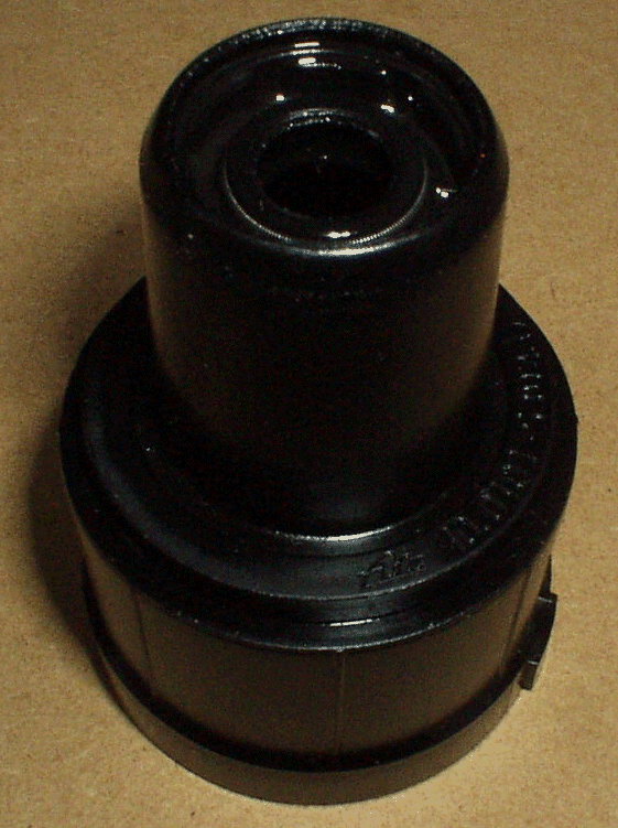
Breakdown of the H31 brake booster
While I had the chance, I
thought I'd take the old ATE H31 booster apart to see if they are really as
"unrebuildable" as everyone says...
Here's the exploded view:
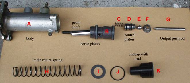
.. Original reason for
failure: leaking from the brake master cylinder end, eg
a failure of the seal in the low-pressure endcap K to
the output pushrod G.
Quick thoughts on
rebuilding:
a) if your booster was
leaking from the pedal shaft, the high pressure seal needs to be replaced with
the new polyurethane unit (Beware - some oil present in the felt ring under the
rubber cap is normal - mine was "misted" or just oily)
b) check the body for scoring in the bore
c) check the white high pressure seal rings on the servo piston
If any of a, b or c are bad, I'm guessing they're not common to find
replacements for...
d) see if you can get a replacement seal for the endcap,
K, and some oil-resistant adhesive to seal it in. I've not tried this, but K
shouldn't see much more than atmospheric pressure anyway
e) get the other 4 internal o-rings (J, 2 from D, 1 from E) and replace
How to get it apart
To get your booster in this
state, you've got to use vice-grips to loosen that little grub-screw on the
bottom of the body - it holds the endcap K in against
the pressure of return spring H. BE CAREFUL - that's a powerful
spring, so use a rag over the end to stop bits flying and don't put your face
close!!
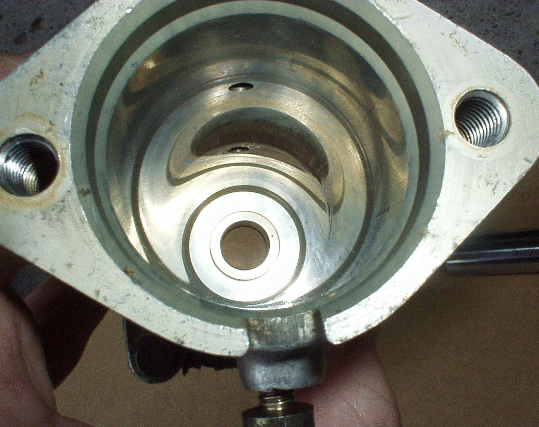
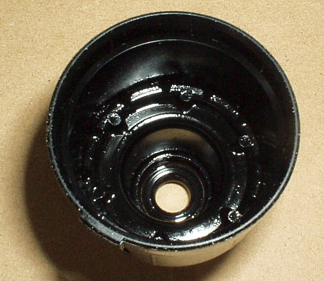
As far as rebuilding
chances go, the bore in the body A and the pedal shaft coming from the servo
piston B are all in great, unscored condition - I
guess the special hard-teflon (I **think** it's teflon) seals - the white rings on B, and another in the
body - are OK, and helped this. They aren't standard, off-the-shelf parts, and
if they were damaged I'd say you would have a hard time replacing them. Here's
the bore of the body, for reference:
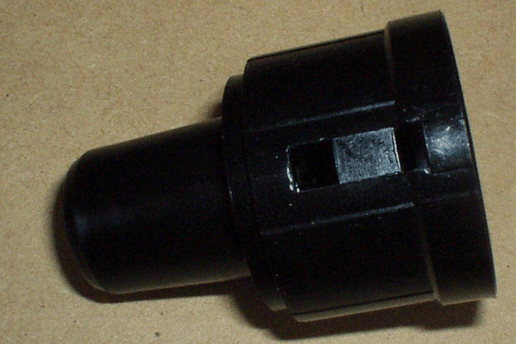
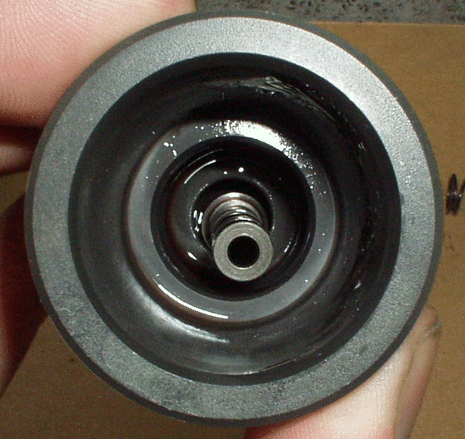
The main culprit for
rebuilding would be the endcap K - here's some
close-ups, the seal seems to be a normal kind of seal, but possibly glued into
the plastic endcap itself:
Remember too that the seal
for the outer edge of the endcap (to the bore) is via
o-ring J which is compressed between the step on the endcap
inside end and the spring-seat washer I.
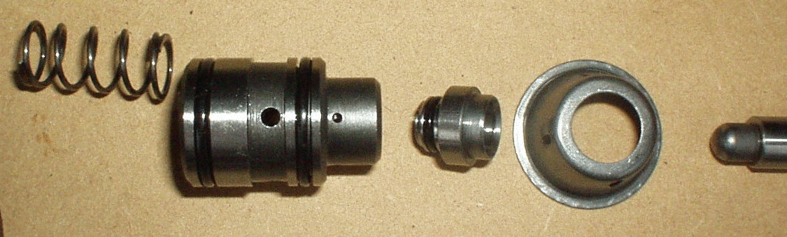
All the other items do have
varying seals, but all of the common o-ring types - since we're using common
ATF I don't think they're any special material, probably just normal neoprene.
The control piston D has 2 on it; it's usually stuck inside the servo piston B,
with the pushrod seat E stuck into its end (E has one o-ring on that
"stuck" end). Wiggle the end of the piston, and spring C will push
the lot out.
Here's these parts in
close-up:
And here's where they fit
into:
Still thinking on the
rebuilding side, here's the details of the high-pressure end of the servo
piston: I think this end is not dismantleable, it
seems to be "staked" (eg edges stamped
over) together.
I wrote this up a while ago
when my BMW 850i discharged a lot of Pentosin 7.1 onto
my driveway. From looking at old postings, it seems often to happen in the cold
weather, and in my case took place a couple months after I replaced my
accumulator. Probably due to the high retained pressures in the system after
that repair. You have to make sure that the discharge is from the small square
"weep hole" at the seam of the master cylinder and booster. That
should be sufficient to properly diagnose the problem. Use a small inspection
mirror for that.
First: Prepare for the job, this repair will drop lots of fluid (brake fluid, Pentosin, and coolant) to the ground between the firewall
and the left front tire. Put a large baking pan under the car at that point to
catch the drippings. There are two parts to the job, one inside the car and one
under the hood. Spend the first hour inside disconnecting things and getting
your bearings, you will be clean and less likely to get grease on the carpet.
Finally, at the end of the job you will need to bleed the brakes so make sure
you have a helper and the room to bleed the brakes.
Tools/Parts:
I use mostly 1/4" drive tools at this point in my life because they are
lighter and easier to use. Specialty tools: 7mm (for bleeding the brakes),
11mm, 14mm and 17mm flare wrenches. 17mm SnapOn
3/8" crowfoot flare wrench (part number FRHM17). 13mm, 1/4" drive,
flexible joint socket (Sears part number 00943199000).
1 liter of Pentosin 7.1 or 11.2
1 can of brake fluid
Coolant (not much is lost).
I also replaced the two grommets that
seal the brake fluid reservoir to the master cylinder, but not necessary
Procedure:
1) Set the wipers to vertical
2) Ignition off, pump brakes 15-20 times till hard to discharge system
pressure.
3) Remove interior trim, including 2 plastic screws near pedals (rotate 90
degrees); 2 plastic screws on under side of leather trim; 2 plastic screws on
left foot rest; open hood and remove single screw in center of hood release
lever on the left foot rest. Remove lever, foot rest, leather trim (careful,
there is Velcro along the console, and three retaining pins along the top), and
pedal cover. Your remote entry module may be attached to the top of the cover,
if so, disconnect the electrical connector and set these parts aside. There is
also an air duct that is in the way. It is held in place with a single screw.
Remove it and look at the brake pedal assembly.
4) Under hood: remove four screws the hold the cabin intake cowling cover in
place, then the two screws that hold the cowling in place and remove the
cowling. Next remove the plastic cover to the heater valve solenoids, the two
electrical connectors to: a) the solenoids, and b) the auxiliary pump. The
latter is on a flimsy plastic holder mounted to the firewall with a Phillips
screw. Careful, don't break or lose this. There are two brake regulator
pressure switches with two contacts each. Remove the contacts and note where
they go. Remove the three 'Acorn' nuts that hold the solenoid assembly in
place. Gently lift this assembly and note that there are three hoses to the
car, two on the front and one to the center fitting of the pump. Remove the
clamps to these three hoses and using three fine wine corks reclamp
the hoses. Not much coolant will be lost. Remove and set aside the solenoid
assembly. Next, disconnect the brake reservoir cover and using a turkey baster, remove all of the brake fluid. Remove the reservoir
by gently rocking it back and forth (I had to pull pretty hard on mine).
6-speeds have an extra blue hose off the back of the reservoir to supply
hydraulic fluid to the clutch master cylinder. NEVER drip brake fluid on paint,
it removes it. If you drip some on a painted surface, thoroughly wash down the
spot immediately (I keep a wet rag handy because its hard not to drip). Now,
step back and look at what is left, inside and outside the car. Rest for a bit.
Outside there is the master cylinder and booster assembly about 18 inches long.
Inside (using a good flashlight), you will see three 13mm nuts that hold the
booster to the firewall and perhaps the fourth one on the upper left. That one
is the most difficult to get at. This is where the 13mm flex wrench comes in.
Also figure out the clip that holds the clevis pin in place on the brake pedal.
5) Take a look at what you need to do outside: there are two brake lines
mounted to the side of the brake master cylinder (11mm) and one high pressure
and one low pressure Pentosin lines mounted to the
top of the brake booster (17mm). All of these need to be removed in order to
get the assembly free. For me the most difficult one was the high pressure 17mm
flare fitting on the booster. That is where I had to use the crowfoot wrench
with an 8" extension. Remove the 4 nuts inside and the fittings under the
hood and you can remove the assembly. There is also a plastic cable holder on
the side of the master cylinder. Disconnect anything else that gets in the way.
I used some hanger wires as retractors to pull hoses and cables out of the way.
Repair:
Keep everything very clean using clean towels and rags, this is your brake
system. On work bench remove the two bolts that hold the master cylinder to the
booster. Mine were held in place with LocTite so I
had to use a flare wrench to remove them. There is a small ratcheting screw on
the bottom front of the booster. With a rag to catch the oil and spring, remove
this screw carefully. The spring has a lot of tension so be careful when you
release the small screw. Keep track of the orientation of the inside parts. The
offending O-ring is held in place by a big washer, so simply replace it with the
one from NAPA, clean everything and reassemble. Putting the spring and cap
assembly back in the booster is a bit tricky but the little retaining screw can
be partly threaded in. Make sure that screw goes into the slot in the plastic
cap and that the pushrod seats properly.
This is a perfect time to replace the spark plugs on bank 7-12. I did because
it is the "only way to get to plugs 11 & 12. Take my advice and do
this now, you will never regret it.
Bleed the brakes after assembly and also the Pentosin
system using the Pentosin bleeder valve on the
bracket with the pressure regulator (850s only). Do this one with the 11mm and
14mm flare wrenches and the engine running. Very easy.
Procedure is somewhat different for an 840, because the booster has an addtional high pressure fitting on the bottom.
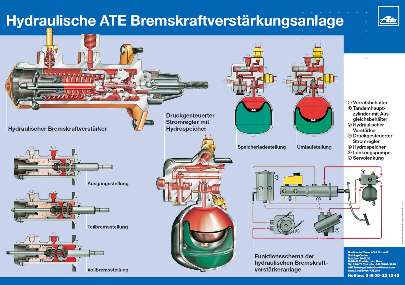
BMW 8
Series – H31 Power Assist System
This month I
want to discuss a somewhat vintage BMW power brake system, the H31 “Hydro
Boost” power brakes and steering system. BMW has always been a leader in technology
and never was this more evident then when they introduced the H31 system in the
E23 seven series cars in 1977. As is still typical the technology that was
debut on the flagship Seven series became a proven design and used on various
Five, Six and Seven series cars ending on the Eight series before being phased
out with the last of the Eight Fifties in the mid nineties. Over the years I
have received a great deal of calls and e-mails regarding the diagnosis and
repair of this system. I will attempt to clarify some of the misconceptions and
advise on accurate, straightforward diagnosis. Unlike almost every other power
assist braking system that uses engine vacuum to create the boost, the H31
system used hydraulic pressure from a special power steering pump to create the
assist needed. This system allowed for more available assist that was highly
controllable in a smaller package then any vacuum boost system available at
that time. Soon after its introduction, BMW coupled its race proven BOSCH ABS
technology to offer a braking system that became the performance standard that
other manufactures where judged by. Over the years the H31 system has caused a
number of headaches for techs who where attempting to diagnosis this very
sophisticated hydraulic system. Most of these headaches are due to a lack of
understanding of the basic principles of operation. The original repair
information involved the use of very high pressure gauges to test the pump
output and the pressure controlled flow regulator known as the DS Regulator
with its attached accumulator better known as “the Bomb” because of its
cannonball shape. I have found the use of these gauges to be unnecessary in all
but a few rare cases. The most common failure of this system is the accumulator
(the bomb). It is a round steel chamber with a high-pressure nitrogen filled
balloon built inside it. On a normal working system, as the pumps hydraulic
pressure builds up it moves fluid into one side of this sphere displacing the
balloon and storing pressure and a volume of fluid. Over time the balloon loses
its nitrogen charge causing the sphere to lose its spring affect of storing the
pressure energy. The simple test of the bomb is to run the car for a minute to
allow the pressures to normalize then shut off the engine and then pump the
brake pedal until all power assist is lost and the pedal becomes hard.
Typically a good accumulator will give you about eight pumps of the brake pedal
before you loose assist. A bad one will be hard after one pump and the
accumulator needs to be replaced. The second part of the test is to check the
DS regulator. Again run the motor briefly to build pressure then shut it off.
Now wait five minutes before applying the brakes. You should have at least half
the pumps with assist that you had when you did the test the first time. If not
the valves in the DS regulator are leaking down to quickly. The DS regulator
cannot be serviced and would need to be replaced. The common symptoms of a
failed accumulator can be an intermittent brake warning light that can come on
when the brakes are applied, or a too soft brake pedal that does not improve
after bleeding the brake hydraulics. A good check for the brake hydraulics is
to pump the pedal till all boost is gone, then if the pedal is still spongy then
the problem is in the brakes. Other issues common to the booster system are
leaking pressure switches at the DS regulator and leaks at the hydraulic
booster. The brake booster leaking will vent power steering fluid (either ATF
or Pentosin depending on the system) at a drain hole
between the booster and the master cylinder. The power steering pump supplying
the pressure for this system has a maximum operating pressure of about 130 bar
(1900 psi), however the working pressure for the H31 system is regulated at 35
57 bar and only needs about ten percent of the fluid volume that is needed for
the power steering. With that in mind it is obvious that any problem with the
pump pressure or volume would show itself first as a problem in the power
steering. To properly check the fluid level you must have the engine off, pump
the brakes until the assist is gone then remove the cover from the reservoir.
The fluid should be at the top of the screen. If not top off with the correct
fluid for your car, most early cars used ATF but later BMW’s went to Pentosin fluid, do not mix them and NEVER use brake fluid
in the pump hydraulics. Brake fluid will destroy the seals in the H31 system
and ATF or Pentosin will destroy the seals in the
brake hydraulics. They are separate systems and do not share fluids, IF IN
DOUBT ADD NOTHING. If either system is contaminated by
the other it can be very expensive to fix and potentially dangerous. My last
set of problems, are usually listed as power steering complaints. This system
uses a very high-pressure, high volume pump; any leaks in the system can be a big mess fast. Many
of these cars develop noises in the pump and the pump is replaced only to find
that the noise is still there! The problem is from air being pulled into the
pump through loose hose connections on the inlet hose between the pump and the
reservoir. The leak can be so small it will not lose any fluid but still allow
air to be sucked in when the car is running. This problem is exaggerated by the
fact that the filter in the reservoir has probably never been serviced and is
plugging up with debris. Finally you must consider the condition of the drive
belt, a belt failure will immediately cause a loss of power steering and the
brakes will only have the stored pressure of the accumulator to assist you for
stopping. You can only imagine heading to the braking zone at turn three of BIR
in your E28 M5 only to find that the belt broke. You would have no power
steering and no power brakes if the accumulator were bad. No more M5, Bad day, really,
really, bad day.
Mo’
later, mo’ better- “Max”